Halloween 2013 Build using a Raspberry Pi
This year for Halloween I wanted to start to scratch the surface of what I could do with a Raspberry Pi in order to bring a “haunted” experience to my front yard. My guidance/inspiration was from here.
Overall, I wanted to have a single motion sensor trigger a sequence of scenes where each scene would incorporate one or more lights, one or more audio tracks and be limited to about 30 seconds or less.
Parts List
I broke the parts list up into two groups, the first is the items you probably would need to buy online, the second you should be able to get most of them from your local Home Depot, Lowes or other hardware store.
Online parts list:


- 6 x Solid State Relays, 3v to 110v+
- Essentially you apply 3 volts to one pair of terminals, which will turn on the 100v pair.

Optional online parts:
- You may need a HDMI (Male) to VGA Adapter if you do not have an HDMI compatible TV or Monitor. To initially install the Pi OS, you will need a way to output the video.
- You may also need some sort of USB keyboard, wired or wireless, most just work. If you don’t have one one hand, you should consider getting one of the smaller form factor wireless keyboards which you can reuse and is portable along with your Pi’s.
- Finally you also need a way to give this device access to your network. If you have a router with a spare LAN port you can use it, just be sure you have a Cat5e networking cable (male on both ends) available for the project. Otherwise a hub will be just as suitable. As an alternative you can find many mini WiFi USB dongles that are compatible for the Pi. I chose to NOT use the WiFi dongle because it is an additional cost. I will not cover of WiFi configuration in this post, there are many online articles outlining the process.
You can buy most of these from adafruit.com, dx.com, or any other favorite retailer.
Hardware store parts list:
-
4 x (double) receptacle wall sockets [NEMA 5-15 (15A/125V
earthed) Type B]

- 3 x electrical boxes
- 1 x single width
- 1 x double width
- 1 x triple width

- 1 x double electrical face plate, “blank” or cover
- 1 x single receptacle wall socket face plate
- 1 x triple receptacle wall socket face plate

|

|

|
- 20 x twist-on wire connectors

-
1 x Bag of electrical cable staples, probably need 50 to
60

- 1 x bag of wood screws, 3” long, at least 24 screws
- 1 x bag of wood screws, 2” long, at least 12 screws
- 1 x Plywood, 2 feet squared, about 1” thick (bottom base)
- 2 x 2x4, 2 feet in length (sides of base)
- 1 x 1x2 2 feet in length (front)
- 1 x Plywood, 1.5 feet squared, (back / relay anchor)
Box Construction:
Take the base plywood (2x2x2) and secure the 2x4’s to each opposite side. Add the 1x2 to one end, and finally the 1.5 foot squared plywood to the back.
This will form an awkward sided box without a lid. This is by design. It will provide enough room for you to secure the two larger electrical box’s to the front left and right, and the smaller box on the left side, in the middle. Finally each relay can be secured to the back / relay anchor piece.
Since a picture is worth a thousand words, here are a few to help out.
|
|


Notice the smaller receptacle box on the left. It is “Always On”, meaning we hardwire power directly to both of those receptacles. The larger box on the right, with the three pairs of receptacles, those are run through the relay switches. Finally, the box on the front left is where we take the main line from the house, and split it into 7 (Always on, and the 6 via the relays).
Note: If I were to do this box again, I would probably use a terminal strip, instead of the lower left box to split the house main into the 7.

Here is a photo of the same box, with the relay switches installed:

Next secure your relay switch’s to the back, like you see in the above picture. Do your best to make them level, straight and in the middle of the box.
Take your 50 feet of electrical wire and run a single line to the Always On box, and then 6 to the back, up and over, and then down and forward to the 6 receptacles on the front right. You will need to split the “HOT” of each of these lines up on the back and wire each HOT into the relay switch. Take care to find out online which exact color is “HOT” / “Phase” / “Live” for your house electrical wiring. For example, in Canada, black is set to be “Live” or “HOT”. Split it, to the set of terminals on the relay switch. Notice I also use secure each split with an appropriate and twist caps.
Use the electrical staples to secure each line down to the box as best as you can, and clean up the box until you are happy with it.


Raspberry Pi Construction
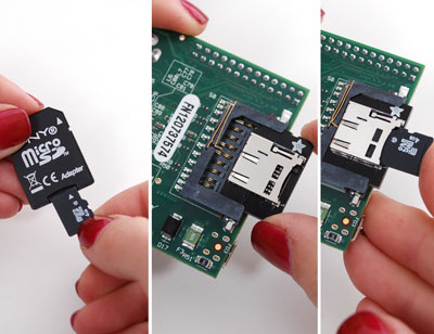
You will need to first download the NOOBs installation media, and follow the instructions here to perform the installation of the “Rasbian” operation system. It is essentially Linux slimmed down for the Pi. Be sure to use the MicroSD card you ordered for the project earlier.
Now unbox the RaspberryPi, MicroSD Adapter, and USB Power. Plug your MicroSD card into the adapter, and that into your Pi. I personally use the HDMI output to my living room television, and you will need some sort of video to perform the initial install on the Pi itself; ensure that this is plugged in as well. Make sure you also plug in your keyboard and your networking cable from a switch or router.
Finally apply power to the device with your USB Power adapter.
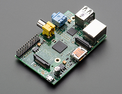
If it is not that obvious of what is what on the Pi, here is useful image outlining the position of each component.
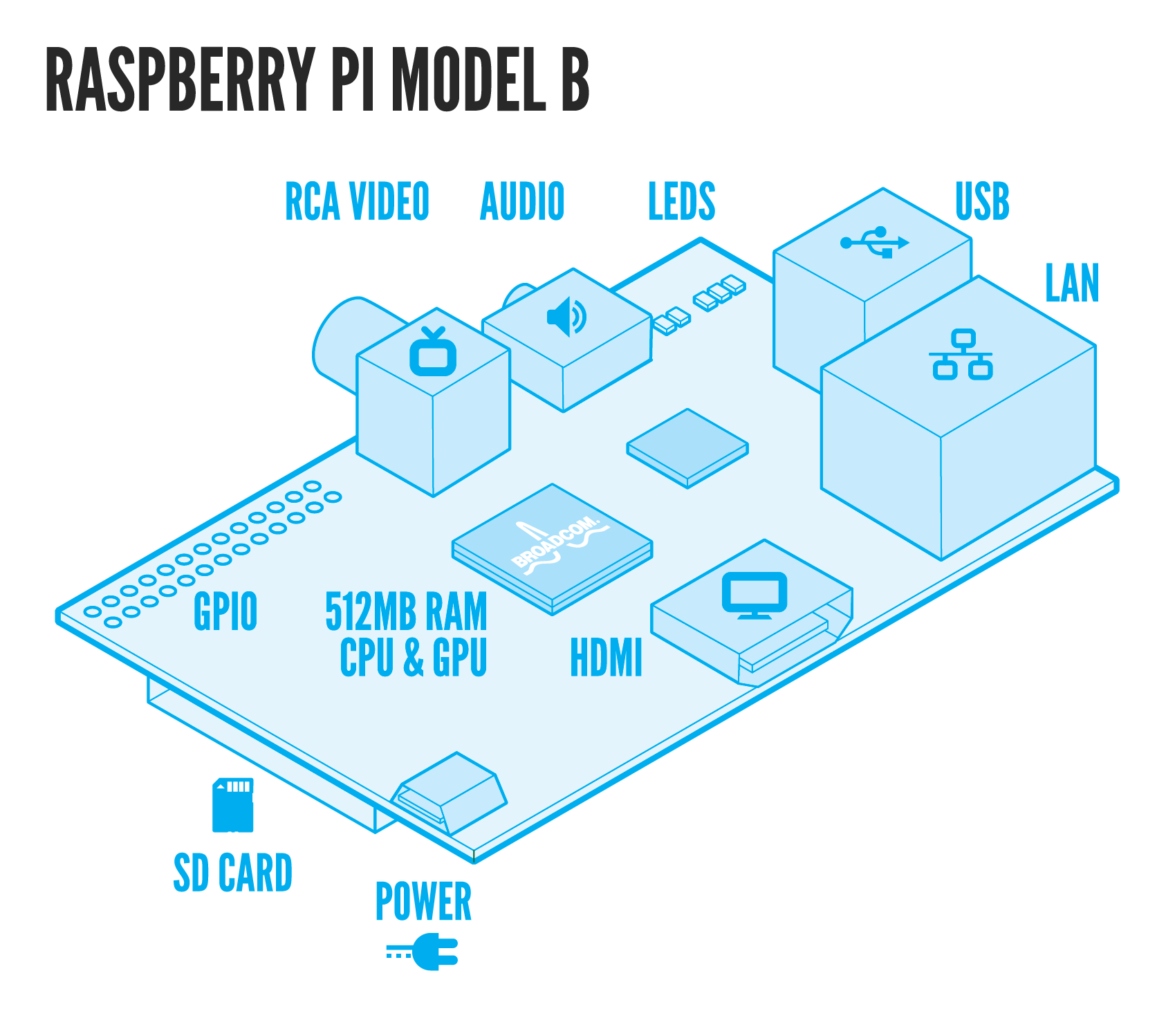
NOTE: The Raspberry Pi does not have any sort of onboard protection for hot-swapping anything from USB, HDMI, or other GPIO Ports. Make sure you shut the device down appropriately before trying to plug anything in or out of it. Failing to do so may result in frying the little guy!
Follow the instructions to finish the installation of the “Rasbian” operating system, and eventually you should end up at a login prompt. Take note of the IP Address, it should be near the login prompt. Login with the default user name and password (pi / raspberry) for the Rasbian operating system. If you missed the IP Address on the login screen, use the command “ifconfig” in the terminal, its output will contain the device’s IP address.
Right now you should be able to login to the Pi, via SSH. If you are on Windows, putty is a suitable tool which you can SSH into the machine. Use the IP address to connect via putty to SSH on your Pi.
Raspberry Pi & Python
Rasbian comes with python already installed, test it out by typing:
python
At the command prompt, which then you should end up in the python “RELP” (Read, Eval, Print, Loop), try this command:
>> import this
You should see “The Zen of Python”, some guidelines for writing python code.
1: >>> import this
2: The Zen of Python, by Tim Peters
3:
4: Beautiful is better than ugly.
5: Explicit is better than implicit.
6: Simple is better than complex.
7: Complex is better than complicated.
8: Flat is better than nested.
9: Sparse is better than dense.
10: Readability counts.
11: Special cases aren't special enough to break the rules.
12: Although practicality beats purity.
13: Errors should never pass silently.
14: Unless explicitly silenced.
15: In the face of ambiguity, refuse the temptation to guess.
16: There should be one-- and preferably only one --obvious way to do it.
17: Although that way may not be obvious at first unless you're Dutch.
18: Now is better than never.
19: Although never is often better than *right* now.
20: If the implementation is hard to explain, it's a bad idea.
21: If the implementation is easy to explain, it may be a good idea.
22: Namespaces are one honking great idea -- let's do more of those!
23: >>>
In order to exit the python REPL, you need to hit Control-Z.
Creating your first python script
- 1. At the SSH prompt, type:
- touch hello.py
- chmod +x hello.py
- nano hello.py
“touch hello.py” will create a new, empty file in the current folder.
“chmod +x hello.py” will set the “execute” flag on hello.py, this allows us to execute it directly.
“nano” is a simple text editor available on the Pi, you should be in the editing window, “hello.py”, which is now empty. Type in the following code:
1: #!/usr/bin/env python
2: print("Hello, world")
Save the document by hitting Control-O, then hit enter. To exit, hit Control-X. This should dump you back out to the command prompt. In order to execute our script we type:
./hello.py
This should simply print out “Hello, world”, and then exit you back to the prompt.
Success!
Also installed by default is the ability to use the GPIO (General Purpose Input/Output) ports in python. We will use the GPIO ports to apply 3v’s to our Solid State Relays.
You will notice that on the PI, there are two rows of Pins sticking out, these are the GPIO pins, here is a diagram which explains each Pin:

Take note of all of the Green GPIO pins. They are what we will be connecting to our Relay Switch’s. We will cover more about these GPIO pins and Python in a section further down.
Raspberry Pi and the Box
Wiring the Pi up to the Box, more specifically the Solid State Relays, is done by first taking a single ground wire from each Solid Sate Relay’s negative/ground terminal (-) to each other in a chain, like the following image.

You can take the Breadboard wires and use them, strip of the plastic tips and about 1/2 inch of the wire sheath to expose the bare metal wire inside. I actually take a single wire from the first to the second, and another from the second to the third and so on, after the final relay you take a final wire out to the Ground pin on the Pi. On this final wire, leave the Female tip which will make it easy to plugin into the Pi. That solves the common ground for each Solid State Relay.
In order to finish this you will need to take a single breadboard wire (female end) from a GPIO port on the PI to the Solid State Relay (male end), positive terminal. Repeat this for each GPIO to Relay terminal. It does not really matter which GPIO port is used, just write each down and their relationship to the final receptacle box of 6.
In the end you will see the following:

Now that you have the Pi online, connected to the Box via the Relay Switch's, and the switch's controlling power to our bank of 6 receptacles, we are ready to start writing more python scripts to control the lights!
Sample Scripts
The best way to get started programming for the Raspberry PI and its GPIO pins is to read over the RPi.GPIO module basics. Please review that prior to continuing.
Below is a set of scripts which should be enough to get you started with working with python and GPIO ports. I did my best to document the code where it was appropriate. If you need more assistance with python there are a plethora of online tutorials which you can learn from.
on_off.py
1: #!/usr/bin/env python
2: import time
3: import RPi.GPIO as io
4:
5: # https://code.google.com/p/raspberry-gpio-python/wiki/BasicUsage
6: io.setmode(io.BCM)
7: io.setwarnings(False)
8:
9: light_one = 24
10:
11: io.setup(light_one, io.OUT)
12:
13:
14: def light(light_pin, state):
15: print("light control:" + str(light_pin) + " " + str(state))
16: io.output(light_pin, state)
17:
18: print("Turning light on")
19: light(light_one, True)
20: time.sleep(1)
21: print("Turning light off")
22: light(light_one, True)
23: print("All done")
allon_off.py
1: #!/usr/bin/env python
2: import time
3: import RPi.GPIO as io
4:
5: # https://code.google.com/p/raspberry-gpio-python/wiki/BasicUsage
6: io.setmode(io.BCM)
7: io.setwarnings(False)
8:
9: light_one = 24
10: light_two = 23
11:
12: io.setup(light_one, io.OUT)
13: io.setup(light_two, io.OUT)
14:
15:
16: def light(light_pin, state):
17: print("light control:" + str(light_pin) + " " + str(state))
18: io.output(light_pin, state)
19:
20: print("Turning lights on")
21: light(light_one, True)
22: light(light_two, True)
23: time.sleep(1)
24: print("Turning lights off")
25: light(light_one, True)
26: light(light_two, True)
27: print("All done")
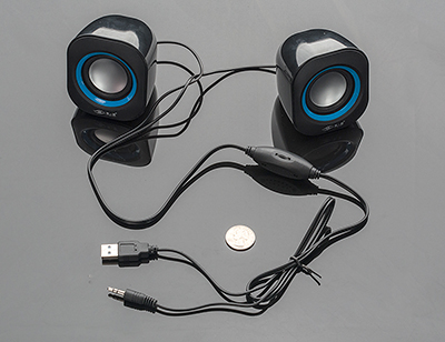
That should be enough to get you started with controlling your receptacles. Next we dive into some sample code for playing sound. Plug in your speakers to the audio jack. I found some sample sound bytes online, and used Audacity to convert them to 2 Channel MP3s if they were not already in that format.
playsound.py
1: #!/usr/bin/env python
2: import pygame
3: import os
4: import time
5:
6: pygame.mixer.init()
7: pygame.init()
8:
9:
10: def playTrack(track):
11: print("playing track:" + track)
12: pygame.mixer.music.load(track)
13: pygame.mixer.music.play()
14: while pygame.mixer.music.get_busy():
15: time.sleep(0.5)
16:
17:
18: print "ready to rock"
19:
20: while True:
21: for files in os.listdir("."):
22: if files.endswith(".mp3"):
23: print files
24: sound = raw_input("Song? ")
25: playTrack(sound)
26: time.sleep(1)
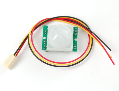
Our last sample script demonstrates using the PIR motion sensor with the Pi, in this example I’m using GPIO port 25. Notice that it is setting the io port to io.IN instead of io.OUT like our switch’s above.
motion.py
1: #!/usr/bin/env python
2: import time
3: import RPi.GPIO as io
4:
5: io.setmode(io.BCM)
6: io.setwarnings(False)
7:
8: pir_pin = 25
9: io.setup(pir_pin, io.IN)
10:
11: def onMovement():
12: print("movement!")
13:
14: print "ready to rock"
15: while True:
16: if io.input(pir_pin):
17: onMovement()
18: time.sleep(300)
In this script we setup an infinite loop with the “While True”. This allows for our script to sit and wait for motion. Once the PIR detection motion we immediately call the “onMovement” function.
Remember for each script file you create to run the “chmod +x script.py” on the pi. This will allow you to test it by just running the script name itself at the command line:
[$] > playsound.py
Putting it all together
Here is my final script for executing scenes based on motion.
1: #!/usr/bin/env python
2: import time
3: import RPi.GPIO as io
4: import pygame
5: import subprocess
6: import time
7:
8: io.setmode(io.BCM)
9: io.setwarnings(False)
10:
11: pygame.mixer.init()
12: pygame.init()
13:
14: pir_pin = 25
15: light_4 = 4
16: light_17 = 17
17: light_18 = 18
18: light_23 = 23
19: light_22 = 22
20: light_24 = 24
21:
22: playing = False
23: io.setup(pir_pin, io.IN)
24: io.setup(light_4, io.OUT)
25: io.setup(light_17, io.OUT)
26: io.setup(light_18, io.OUT)
27: io.setup(light_23, io.OUT)
28: io.setup(light_22, io.OUT)
29: io.setup(light_24, io.OUT)
30:
31: def allOff():
32: light(light_4, False)
33: light(light_17, False)
34: light(light_18, True)
35: light(light_22, False)
36: light(light_23, False)
37: light(light_24, True)
38:
39: def scene1():
40: print "scene 1, scream"
41: light(light_22, True)
42: playTrack("scream.mp3")
43: light(light_22, False)
44:
45: def scene2():
46: print "scene 2, baby"
47: light(light_17, True)
48: playTrack("rosie.mp3")
49: light(light_17, False)
50: time.sleep(2)
51:
52: def scene3():
53: print "scene 3, torture"
54: light(light_4, True)
55: playTrack("torture.mp3")
56: light(light_4, False)
57:
58: def endScene():
59: light(light_24, True)
60: light(light_23, True)
61: playTrack("laugh.mp3")
62: time.sleep(2)
63:
64:
65: def onMovement():
66: print("movement!")
67: light(light_18, False)
68: scene1()
69: scene2()
70: scene3()
71: endScene()
72: allOff()
73:
74:
75: def light(light_pin, state):
76: print("light control:" + str(light_pin) + " " + str(state))
77: io.output(light_pin, state)
78:
79: def playTrack(track):
80: print("playing track:" + track)
81: pygame.mixer.music.load(track)
82: pygame.mixer.music.play()
83: while pygame.mixer.music.get_busy():
84: time.sleep(0.5)
85:
86:
87: allOff()
88:
89: print "ready to rock"
90: while True:
91: if not(playing):
92: if io.input(pir_pin):
93: print "starting"
94: playing = True
95: onMovement()
96: playing = False
97: print "ended"
98: time.sleep(300)
Action!
A video of the build in action:
That’s all for now!