Authoring SVG with a text editor
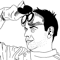
 SVG definitely is an increasingly interesting skill, especially as it's making its way into HTML 5 as an officially allowed grammar inside of HTML documents. Most SVG is authored through some kind of tool, and it's absolutely the way to go for artistic drawings. I used Inkscape (open source) and Expression Design in the past for that (I can't afford Illustrator), and I've been happy with the results (to your right and left).
When you are doing this kind of artwork, the quality of the generated SVG doesn't matter much, and well, it's a good thing as what those tools spit out is rather horrendous. Think HTML from Word.
There is a category of drawing though that is better authored by hand, because it needs to be human-readable and tweakable, and because it requires a level of precision in coordinates that would be tedious to achieve in a tool. A lot of technical drawing enters this category.
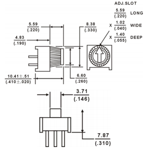
 One of the things I do outside of work is electronics. I use Fritzing to design printed circuit boards (PCBs), and it's an excellent open source tool, but its library of components is not as complete as what can be found in commercial offerings, so I have to author some of the components I need myself. Today I'm working on a very simple one, a potentiometer I got from Sparkfun (illustration to your right).
Fritzing has three views: breadboard, were components are drawn in a semi-realistic fashion, schema and PCB. In this post, I'm going to explain how I built the breadboard view of the potentiometer.
At the beginning of the document is some rather uninteresting doctype declaration:
<?xml version="1.0" standalone="no"?>

<!DOCTYPE svg PUBLIC "-//W3C//DTD SVG 1.1//EN"
"http://www.w3.org/Graphics/SVG/1.1/DTD/svg11.dtd">
Then we have the svg tag where, apart from some namespace declarations, the size of the document is declared:
<svg width="9.53mm"
    height="9.53mm"
    viewBox="0 0 953 953"
    id="TSR3386U-T_Breadboard"
    version="1.1"
    xmlns="http://www.w3.org/2000/svg"
    xmlns:xlink="http://www.w3.org/1999/xlink">
 We define the size in millimeters here to make the design from the component's datasheet as easy to translate as possible. The viewport attribute is here to map a system of coordinates on these dimensions. The values we set here maps 9.53mm to 953 coordinate steps. The result of this is that a coordinate of 100 will be a millimeter from the origin (all the other coordinates in the document will be without units and will use those proportions). This also means that you can resize the whole document from this single place.
A very important construct to understand in SVG is groups, represented by <g/> tags. This allows us to make logical grouping of forms and give structure to the document. For Fritzing components, I put a group with id "breadboard" around all shapes to identify the breadboard view of the component. Inside of that group, I have subgroups for the outline of the component, and another for the shapes forming the knob.
The outline is made of a single filled path tag:
<path
   style="fill:#0000A0;stroke:none"
   d="m 0,0 l 953,0 0,953 -75,0 0,-38 -803,0 0,38 -75,0 z" />
The style is self-explanatory (and familiar if you know CSS), but the unexpressive d attribute demands more attention. It describes the path using a small DSL. Each command in the path DSL consists in a letter and a set of coordinates. The convention is that a lowercase letter is used for relative coordinates, and uppercase is for absolute coordinates. We use relative coordinates here. We start by moving (m command) the pen to the top-left corner (0,0), then we draw lines (l command) 9.53mm to the right, 9.53mm down, 0.75mm left, 0.38mm up, 8.03mm left, 0.38mm down, and 0.75mm left. Then z (like zero) closes the path.
The design of the knob needs three concentric circles, an arrow on top and small grooves around the knob. When adding the shapes for each of those elements, it's important to order them from the bottom up as SVG uses that to determine how overlaps are handled. The circles are simple shapes, described by the coordinates of the center (cx, cy) and the radius (r):
<circle
   style="fill:none;stroke:black;stroke-width:20"
   cx="476.5" cy="419" r="419" />
The grooves around the knob are more interesting. They are thin lines going from the center of the knob, all around it. We could draw each line by computing its extremities' coordinates, but that would be no fun at all. Fortunately, SVG has a special tag, <use/>, that can make clones of other elements, simple or complex, and apply geometrical transforms to them. So all we have to do is draw one line, and then we can rotate copies of it for all the others.
<line id="grooveception0"
    style="fill:none;stroke:black;stroke-width:5"
    x1="476.5" y1="419" x2="57.5" y2="419" />
Here's a use tag that takes the line above and rotates it 4 degrees around the center of the knob:
<use xlink:href="#grooveception0" transform="rotate(4, 476.5, 419)" />
The transform here is a simple rotation specifying the angle in degrees, and the x and y coordinates of the center of the rotation. Now we could make 88 more copies of this to complete the circle but that would be boring. Instead, let's divide and conquer, and make increasingly big recursive copies of the grooves.
<g id="grooveception5">
 <g id="grooveception4">
  <g id="grooveception3">
   <g id="grooveception2">
    <g id="grooveception1">
     <line id="grooveception0"
       style="fill:none;stroke:black;stroke-width:5"
       x1="476.5" y1="419" x2="57.5" y2="419" />
     <use xlink:href="#grooveception0" transform="rotate(4, 476.5, 419)" />
    </g>
    <use xlink:href="#grooveception1" transform="rotate(8, 476.5, 419)" />
   </g>
   <use xlink:href="#grooveception2" transform="rotate(16, 476.5, 419)" />
  </g>
  <use xlink:href="#grooveception3" transform="rotate(32, 476.5, 419)" />
 </g>
 <use xlink:href="#grooveception4" transform="rotate(64, 476.5, 419)" />
</g>
<use xlink:href="#grooveception5" transform="rotate(128, 476.5, 419)" />
<use xlink:href="#grooveception5" transform="rotate(256, 476.5, 419)" />
The neat thing about this method is that the number of copies necessary only grows with the logarithm of the number of grooves. In our case, we have 7 use tags instead of 89.
And this is pretty much it. I'm attaching the finished SVG file to this post so you can check it out in its entirety, and here is the result:
Download the SVG file:
http://weblogs.asp.net/blogs/bleroy/Samples/TSR3386U-T_Breadboard.zip